New Customer?
Create your accountNo products
Prices are tax included
Tutorial DIY - Power cable ELECAUDIO CS-331B
DIY Tutorial- Cable assembly
_1.jpg)
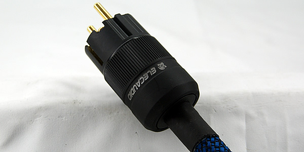
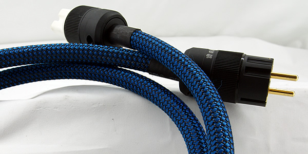
ELECAUDIO CS-331B Power cable
(Updated on 25/07/2016)Introduction
The purpose of this tutorial is to help you create an Audiophile power cable based on the ELECAUDIO CS-331B model, our very high-performance proprietary cable that you can acquire by the meter through us alone. The estimated assembly time for this cable is 45min to 1h30, depending on your tinkering habits.
In all consistency, and to ensure perfect compatibility between the different elements, the Schuko and IEC terminations are also products from the ELECAUDIO catalogue, namely the PS-22G and PI-22G models. Similarly, the outer sheath used is our model called "Electric Blue", a sheath that will not necessarily be unanimously accepted because of its extravagance, but that you will always be able to replace with any other nylon sheath with a suitable diameter, i.e. a minimum of 14mm.
Before going through the steps of this tutorial, here is a brief reminder of the technical specificities of our products:
Elecaudio CS-331B
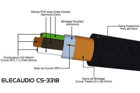
- Individual composition of the components: 7x10 OFC copper wires of 0.25mm diameter
- Composition of the shielding sheath: 24x9 Braided copper wires 0.12mm in diameter
- Conductor diameter + PVC individual sheath: 4.30mm
- Total cable diameter : 13,5mm
- Color : Shining black
Elecaudio PS-22G
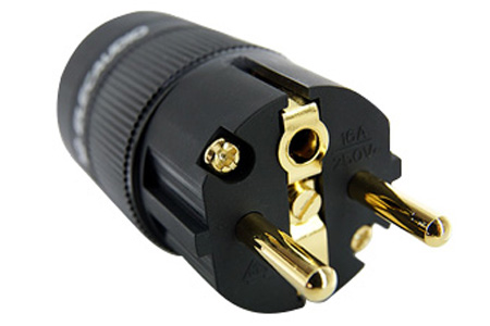
- Schuko socket: 3 screw contacts
- Metal treatment: Double plating Silver + 24K Gold
- Maximum conductor cross-section: 28mm² (6mm diameter Ø)
- Maximum cable diameter: 17mm
- Voltage : 6A / 250V
- Cable length : 84mm
- Diameter : 38mm
- Weight : 120g
Elecaudio PI-22G
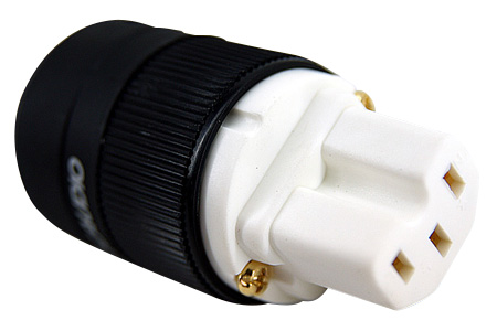
- IEC Socket : 3 screw contacts
- Metal treatment: Double plating Silver + 24K Gold
- Maximum conductor cross-section: 28mm² (6mm diameter Ø)
- Max cable diameter : 17mm
- Voltage : 16A / 250V
- Total length : 72mm
- Diameter : 38mm
- Weight : 110g
People wishing to start building such a cable will not necessarily have to buy these components individually since we have planned several packages combining both the connectors and the cable available in several lengths (1.5m - 3m - 5m). In addition to simplifying ordering, these packs make it possible to make significant savings on the purchase of separate elements (around 20%). It is then up to you to complete them, or not, with a girdle in custom colours and patterns.
Required components
- Elecaudio CS-331B : Triple shielded power cable 3 x 3.5mm²
- Elecaudio PS-22G : Silver and Gold double plated Schuko socket
- Elecaudio PI-22G : Silver and Gold double plated IEC socket
- Elecaudio EB-05 : Stretchy braided sheath Nylon (PET) 7-14mm
- Silver or Gold plated 6mm² crimping tips
- Standard Aluminium foil or flame-retardant adhesive tape (PTFE, fiberglass...)
Required tools

- Thermal scraper
- Crimping tool
- Stripping pliers
- Cutter
- Cutting pliers
- Flat & Phillips screwdriver
- Cisors
Safety instructions

Although accessible to the greatest number of people, the design of a power cable, whose purpose remains to carry a potentially deadly current, requires a minimum of dexterity in the movements, and above all a maximum of concentration and seriousness throughout the process. Therefore, it is preferable for people wishing to embark on such a project to have at least some experience in handling sharp and/or dangerous tools such as a cutter, a cutting pliers, or a thermal scraper whose output temperature can be around 400°!
The list of tools available above is intended solely to help you carry out your project, and does not constitute in any way an imperative for its successful completion. For example, the thermal stripper can be replaced by a hair dryer of reasonable power as long as its operation seems compatible with the most elementary safety rules. More generally, avoid risky behaviour during this delicate step of sealing heat-shrink tubing, such as using a lighter or other heating device with a flame or resistance that can come into contact with the cable or any of its components.
Take the time to prepare your workspace to perform the various operations detailed below in a stable, clean environment free of any successive elements that could interfere with your actions, or cause an accident by collision, thermal, chemical or electrical contact. AUDIOPHONICS and ELECAUDIO shall not be held liable for any human or material damage resulting from a misinterpretation, error of judgment, improper handling or misreading of this tutorial.
Mounting guide
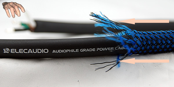
STEP 1 :
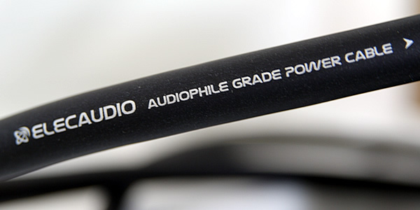
Mark the cable direction using the screen printing on the sheath. The direction of reading the writing and an arrow clearly indicate the assembly to be respected for maximum efficiency:
Schuko --->--->---> IEC
Now that the position of the connectors has been identified, we will be able to start preparing the cable by integrating the Schuko plug.
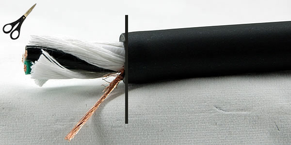
STEP 2 :
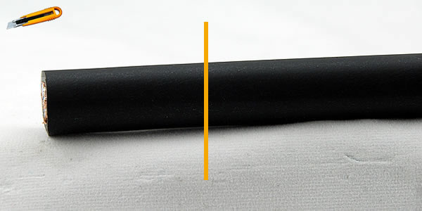
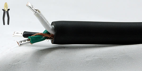
Cut the PVC protective sheath of the cable with a cutter about 30mm from the outer edge. Make sure you draw a circular path as straight as possible, using a pencil if necessary, and then only follow the path.
Be careful not to exert too much pressure on the cutter as this could damage the drain under the copper shielding sheath. A slight contact of the cutter blade with it should serve as a guide as to the force to be used to cut the PVC sheath without damaging the lower layers of the cable.
STEP 3 :
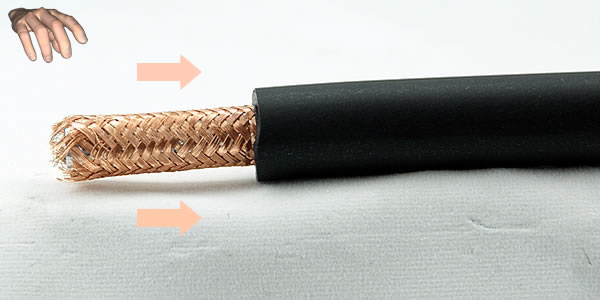
Loosen the copper bars calmly, without tearing off the strands, by pushing them towards the edge of the PVC protective sheath. This handling, if carried out correctly, will allow you to reach the copper drain under the shielding sheath without damaging or fraying it. It is imperative to keep this drain intact and then bring the different strands together in a single twisted bundle.
STEP 4 :
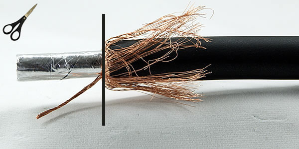
Once the copper drain has been perfectly identified and insulated, cut the shielded sheath wires cleanly with a chisel, now disconnected, to the edge of the PVC protective sheath. Be careful not to damage the drain when handling the scissors. Check one last time that all the wires making up the drain are properly assembled. Attach the few remaining copper sheath wires to the drain by twisting them at the base of the drain.
STEP 5 :
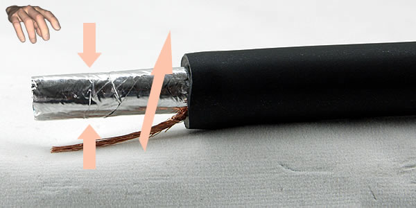
Cut the aluminium strip protecting the 3 conductors at the base of the PVC sheath. To do this, grasp it between your thumb and forefinger, and rotate it in the opposite direction of folding while maintaining a slight pressure. This should allow you to disengage the protective strip and then cut it cleanly with a chisel. It is not recommended to cut the strip with a cutter while it is still plated to the conductors.
STEP 6 :
Cut out the cotton yarns used for padding at the base of the PVC sheath. To get a clean result, grab a small package of these wires with your thumb and forefinger, stretch them slightly outward while holding the cable, then cut them at the base with a chisel. Again, it is strongly discouraged to cut the cotton yarns with a cutter while they are still in contact with the conductors.
STEP 7 :
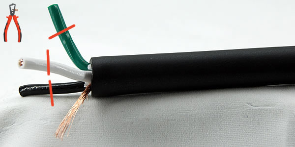
Strip the 3 conductors at 1cm from their ends, the easiest way is to use a stripping pliers to avoid damaging the copper strands of the conductors. However, with a little skill and finesse, a simple cutter also makes it possible to obtain a clean and flawless result.
STEP 8 :
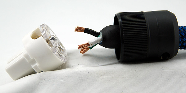
Now that our 3 conductors are cleared and stripped, we can connect the drain connected to the shielding sheath to the ground wire. For Reminder :
- White wire : phase
- Black wire : neutral
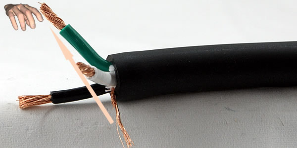
- Green wire : ground
To do this, simply wrap the green wire with this drain until you reach the bare end. Make sure to twist the copper strands carefully to ensure good cohesion.
STEP 9 :
Our cable is on track: The shielding sheath connected in this way will effectively evacuate electromagnetic (EMI) and radio (RFI) interference to earth. This connection is only to be made on the Schuko plug side, a bit like a floating mass. All that remains is to install 6mm diameter crimping bits, such as those supplied in our DIY CS-331B kits, and then attach them at each end with an appropriate clamp.
STEP 10 :
And that's it, our drivers are now ready to receive the power plug. Please note that the crimping inserts are mandatory for assembly in accordance with EC standards, and that their presence is "essential" only on the Schuko plug side for safety reasons. Indeed, the cable clamping system on these sockets is based on a simple screw that crushes the conductor in its center. The IEC sockets, on the other hand, use a more sophisticated locking system in which a large piece of copper plated metal is placed over the entire surface of the conductor.
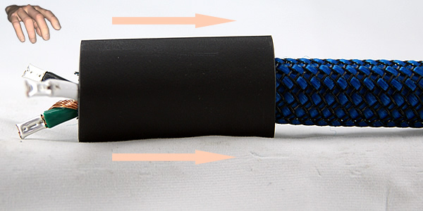
STEP 11 :
We will now be able to cover the CS-331B with its pretty nylon protective sheath. To do this, grasp the other end of the cable, and slide the sheath into it, gradually progressing until it completely covers the PVC. Position the end of the nylon sheath by biting about 0.5cm on the 3 conductive wires on the Schuko side. Then remember to tighten the nylon to avoid unsightly folds. As a reminder, the CS-331B can be covered with any Nylon sheath with a minimum diameter of 14mm.
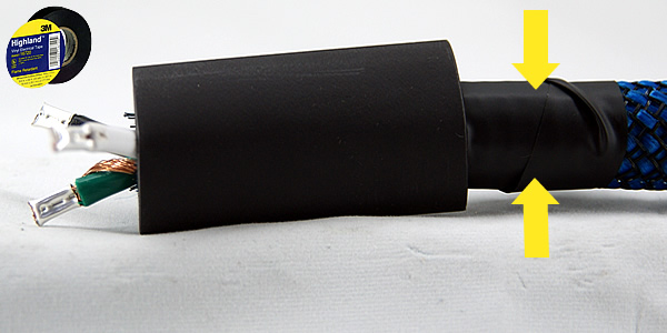
STEP 12 :
Once this is done, cut a strip of heat-shrinkable sheath about 5cm long, and position it at the end of the cable over the nylon sheath. To facilitate the passage of the thermo sheath, you can connect the wires separated from the nylon sheath and immobilize them with a simple piece of insulating tape of the Chatterton type.
Remember that the cumulative thickness of the cable and the nylon sheath implies the use of a thermo sheath with a minimum diameter of 15 to 16mm. For our part, we recommend the use of a 19mm diameter 3:1 model for optimal installation comfort and finish.
STEP 13 :
Before wielding your thermal scraper or hair dryer, remember to protect the nylon sheath well by wrapping it with a heat-resistant adhesive tape (Teflon), or a piece of aluminum foil properly positioned on the periphery of the thermal sheath.
Be careful not to place this protective tape under the thermo sheath, otherwise it will no longer be possible to remove it once the latter has been retracted, especially since the 3:1 models we distribute are equipped internally with an adhesive layer designed to perfect cohesion.
STEP 14 :
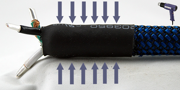
Heat the sheath evenly over its entire length, avoiding stagnating too much in a specific area, even if it seems to have more difficulty shrinking. Take all the time you need, act without precipitation while keeping a comfortable space between the scraper's nozzle and the thermal sheath to avoid excessive exposure to heat. Once the thermo sheath has been correctly retracted, you can gently remove the protective tape..
STEP 15 :
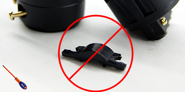
We now have to prepare the Schuko connector to receive the cable. The first step will consist in unscrewing the plug in order to reach a small plastic part located inside the unit, the function of which is to hold the small diameter mains cables in the axis. The CS-331B is not exactly one of them, so we'll have to remove it.
There are a total of 4 screws to be removed with a cross-head screwdriver, 2 of which pass through the part in question before joining 2 threads integrated into a second, slightly wider moving part. The two screws in question must be completely unscrewed to allow the unnecessary part to be released.
STEP 16 :
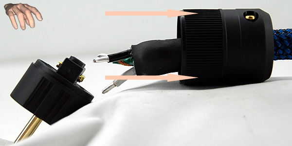
You can now install the Schuko plug at the end of the cable. To do this, start by slightly tightening the 2 screws on the side of the socket at the back of the socket, in order to hold the internal plastic part mentioned above in place.
The passage of the cylinder from the plug to the cable with nylon and thermo sleeves must be done without difficulty. There is no need to force or risk damaging the ducts. If there is resistance against you, it is because the 2 screws securing the internal holding part are too tight, and it is enough to unscrew them slightly.
STEP 17 :
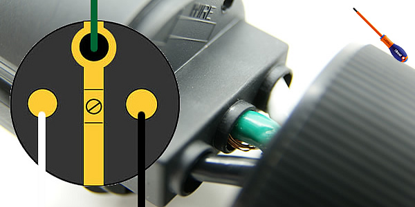
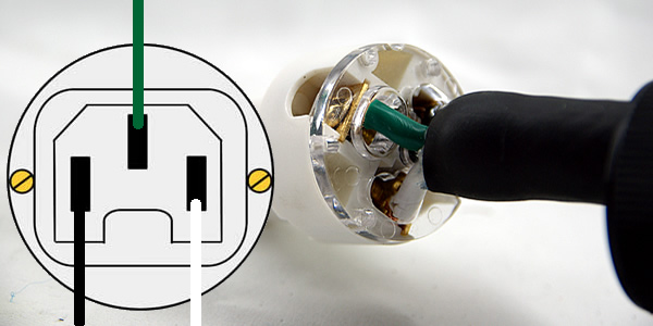
Connect the plug in accordance with the diagram above in order to respect the phase. Unscrew as much as possible the small flat head screws blocking the connection holes, then insert your 3 conductors until you reach the stop. Ideally, and with the exception of the grounded drain, no contact or wire should be visible or protrude from these receptacles. Once the 3 cables are correctly positioned, tighten the screws of each hole firmly to tighten the conductors.
STEP 18 :
All that remains is to join the 2 parts of the grip, helping each other to align them with the markings located internally of each element (small notch on the head of the Schuko, protrusion on the body side). Screw it all back in with a cross-head screwdriver, and that's it, our Schuko plug is installed! We can say that the hardest part is done, the installation of the IEC plug being even less constraining as you will see.
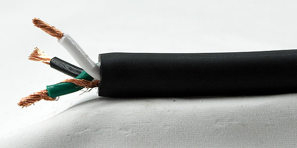
STEP 19 :
For the preparation of the IEC end, repeat the steps 1 to 16 detailed above, with 2 exceptions: :
- STEP N°3 : This time, do not keep the drain, but cut it off like the rest of the shielding sheath.
- STEP N°9 : There is no need for the IEC to install crimped ferrules on the conductors. Just twist the ends cleanly.
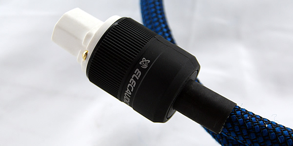
In addition, in step 11, remember to tighten the nylon sheath tightly to avoid creases over the entire surface of the cable. In the end, you should get something similar to the illustration above.
STEP 20 :
Connect the plug in accordance with the diagram above in order to respect the phase. Unscrew as much as possible the large cruciform screws holding the clamping jaws, then insert your 3 conductors between these 2 copper plates until you reach the stop. Ideally, no contact or wire should be visible or protrude from these receptacles. Once the 3 cables are correctly positioned, tighten the screws of each hole firmly to tighten the conductors.
STEP 21 :
All that remains is to join the 2 parts of the socket, helping each other to align them with the markings located internally of each element (large notch on the head of the IEC, protrusion on the body side). Screw it all back in with a cross-head screwdriver, and that's it, our IEC plug is installed! As for the final result...
STEP 22 :
... It's a bit of a big deal... and wait until you hear it! We hope that this tutorial will have been a valuable help in the realization of your ELECAUDIO CS-331B power cable, and wish you long hours of pleasure in rediscovering the musical qualities of your system.
Feel free to contact us in the comments or through the Contact form if you have any questions, we will answer you as soon as possible.
Rechercher dans le blog
Blog categories
Latest Comments

Audiophonics Team
on DIY Tutorial - PiCorePlayer - Installing...
Pierre Bommel
on Lecteur réseau Opensource : Solutions
Pierre Bommel
on DIY Tutorial - PiCorePlayer - Installing...
Audiophonics Team
on Tutorial DIY - Power cable ELECAUDIO CS-331B


![[GRADE B] DAYTON AUDIO MKSX4 Low Profil Subwoofer Speaker 160W Ø20cm](https://www.audiophonics.fr/72897-thumb_default/dayton-audio-mksx4-low-profil-subwoofer-speaker-160w-o20cm.jpg)

![[GRADE S] SHANLING M6 PRO HiFi DAP Compact Music Player DAC 2x AK4497 32bit 768kHz DSD128 Titanium](https://www.audiophonics.fr/72951-thumb_default/shanling-m6-pro-hifi-dap-compact-music-player-dac-2x-ak4497-32bit-768khz-dsd128-titanium-sbs.jpg)
![[GRADE S] SHANLING M0 PRO Compact HiFi Digital Audio Player DAP DAC 2xES9219C Bluetooth 5.0 aptX LDAC 32bit 384kHz DSD Green](https://www.audiophonics.fr/72945-thumb_default/shanling-m0-pro-compact-hifi-digital-audio-player-dap-dac-2xes9219c-bluetooth-50-aptx-ldac-32bit-384khz-dsd-green-sbs.jpg)
![[GRADE S] SHANLING UA1 PLUS Portable USB-C DAC / Headphone Amplifier 2xCS43131 32bit 768kHz DSD512 Black](https://www.audiophonics.fr/72936-thumb_default/shanling-ua1-plus-portable-usb-c-dac-headphone-amplifier-2xcs43131-32bit-768khz-dsd512-black-sbs.jpg)


9 Commentaires
Laisser un commentaireBoris gourbeau 2024-11-09
Faut-il couper à ras de la gaine plastique ou mètre une gaine thermo pour sur le fil de terre pour l'isoler ?
Audiophonics Team 2024-11-15
Il conviendra en effet de l'isoler pour qu'elle ne puisse venir toucher l'une des autres.
SERGE BOTTARI 2024-07-26
Autre question, pourquoi y a-t-il une direction de branchement (s'agissant de courant alternatif ) ?
Merci
Cordialement
Audiophonics Team 2024-07-30
Rien n'interdit de le relier des deux cotés (les audiophiles préfèrent en général que le coté source). les câbles ne sont pas directifs.
Philippe MAURY 2020-02-25
2 remarques: les couleurs des fils secteur noire et blanche pourraient être bleue et rouge (ou marron), pour le neutre et la phase?
2ième point, le connecteur Schuko Elecaudio RS-24GB semble avoir des repérages neutre (N) et phase (L) inversés, pas le connecteur IEC RI-24GB.
Sur la fiche Audiophonics de mon câble secteur en kit (le 5 mètres, réf 4909), le schéma de montage des fils des 2 prises est bien renseigné, j'ai suivi celui-ci.
Cordialement.
Philippe.
Pierre Roy 2019-02-01
Daniel Pluciennik 2018-03-29
Gilles C 2019-07-10
Si votre sujet est tjrs d'actualité, j'ai peut être des infos qui pourrait vous éclairer .
Faite moi signe ;)
Gilles
Christian TOUSSAINT 2018-02-12
cordialement