New Customer?
Create your accountNo products
Prices are tax included
Setting Sigma Studio for Sure / Wondom DSP modules
How to use Sigma Studio with a DSP module from Sure / Wondom
In this tutorial, we will see how to set the SIGMA STUDIO graphic DSP software with a programmer board from Wondom.
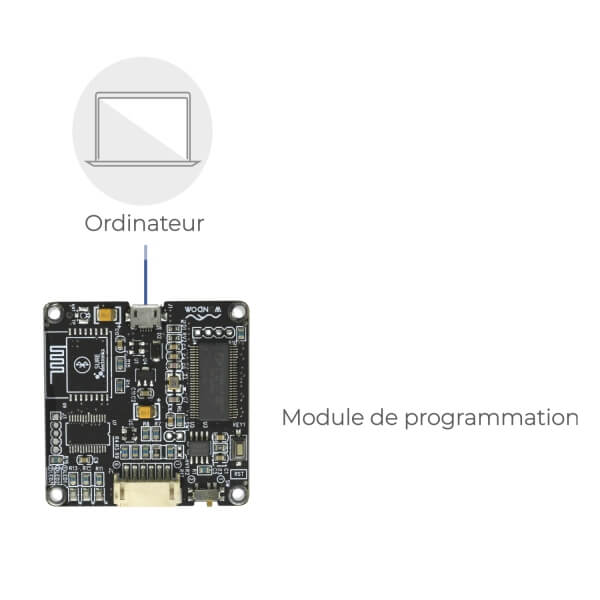
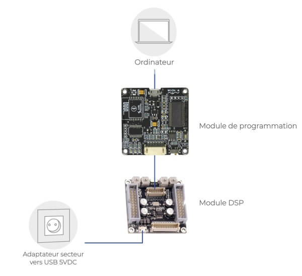
The purpose of this programmer board is to allow a computer to communicate with a DSP module from Sure / Wondom, or even a amplifier module with DSP function (such as the JAB series). The module allows your computer to upload custom digital sound procressing algorithms in your DSP module. When it is done, the DSP runs those algorithms and function by itself.
The following tools are needed to complete this tutorial :
- A Computer
- A DSP Module
- A DSP programmer board
At first the user must write the algorithm on the computer using Sigma Studio Software. When the algorithm is ready the programmer board is used to copy the compiled algorithm to the DSP module own memory.
If you start from scratch, the whole operation can be a little complicated but ADAU1701 chips are well-built and it is almost impossible to damage the hardware with a wrong configuration.
Download and Install Sigma Studio
Start by downloading and installing Sigma Studio from Analog Device website. Follow the instructions of the installation Wizard.
Please note that Sigma Studio only runs on Windows 7 and Windows 10 (last time checked : 2019).
If you are not used to Windows OS, make sure to remember the installation path. (Defaut is C → Program Files → Analog Devices). You might need it if you have trouble installing the driver.
Driver installation
Use a Male USB-A to Male Micro-USB Cable to connect the programmer board to your computer
programmer board does not have a light indicator to show if the device is powered or not, we will soon see how to check if everything is working as it should.
Depending on your computer specifications, wait 2 to 5 minutes. If your Windows operating system is up to date, the driver installation should be automatic and you should see a little notificiation on the bottom-right corner of the screen.
If automatic installation fails (no notification or error notification) do not panic. Go to Sigma Studio installation folder. You will find another folder named "USB drivers". Search fo a executable file named dpinst.exe and follow the instructions to manually install the driver.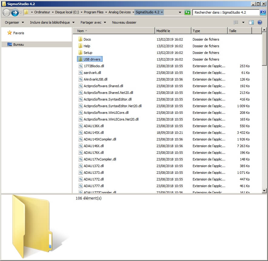
(programmer board must be plugged-in before doing a manual install).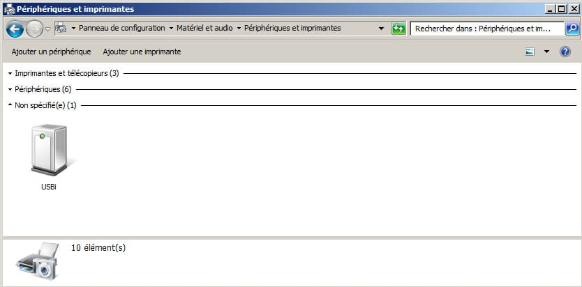
You can confirm that the driver installation is alright by looking in windows control panel. 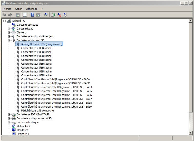
Idem from device manager.
Setting your Sigma Studio project
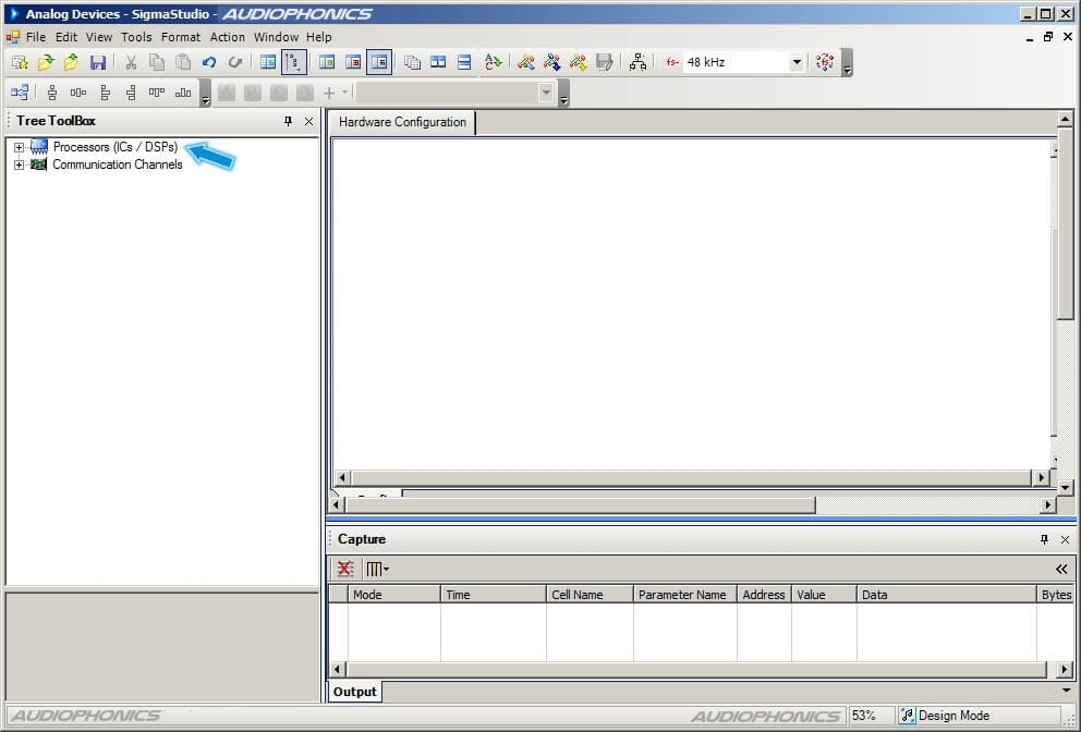
Run Sigma Studio software and create a new project (File → New Project).
Wondom's DSP modules work with a ADAU1701 logical chip and a EEPROM memory. When the programmer board is connected to your computer, it is already possible to control some of the DSP function in real time. However, the point is to copy your instructions on the DSP memory for it to be able to run on its own without a computer or a programmer board.
Sigma Studio can work with very different chips and memory types. The first step is to tell the software what kind of hardware is now used.
At this state, it is not important whether the programmer board is plugged-in or not.
On the left part of the screen, you will find two different trees :
- Processor (ICs / DSPs)
- Communication Channels.
In the Processor (ICs / DSPs) category, look for your chip reference ADAU1701 (with WONDOM DSP). Drag and drop the item from the left panel to the right panel (hardware configuration).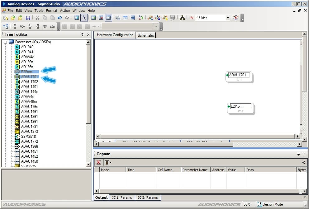
Note that a new tab "Schematic" appears on the main right panel. We will come back to it soon.
Repeat the drag and drop with the entry named E2PROM to let Sigma Studio know what kind of memory your DSP module is using.
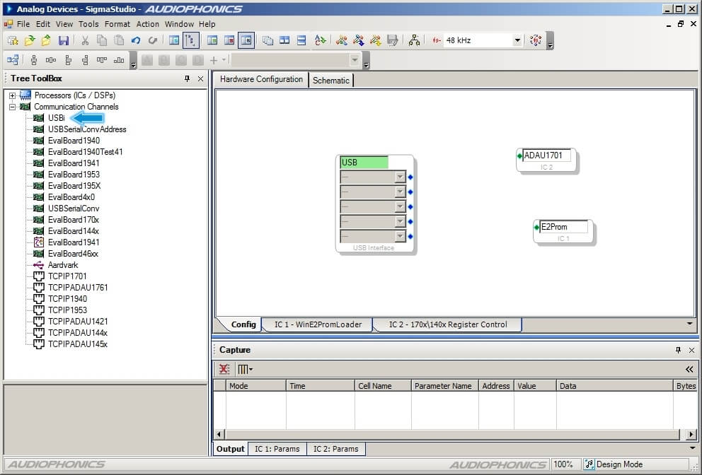
In the Communication Channels category, select USBi (drag&drop as well). This operation defines the communication protocol between your computer and your programmer board (USB in our case).
If it is not the case alreadyn plug your programmer board into your computer with a USB cable (use one that supports data).
Pay attention to the color of the frame labeled "USB". Green means that the software has recognized the programmer board and is ready to go on. If you press the reset button on the programmer board, you will see the label flash in red.
If you have trouble getting the green frame, double check the driver installation. If it still does not work, check you USB cable for damage and make sure data is supported. 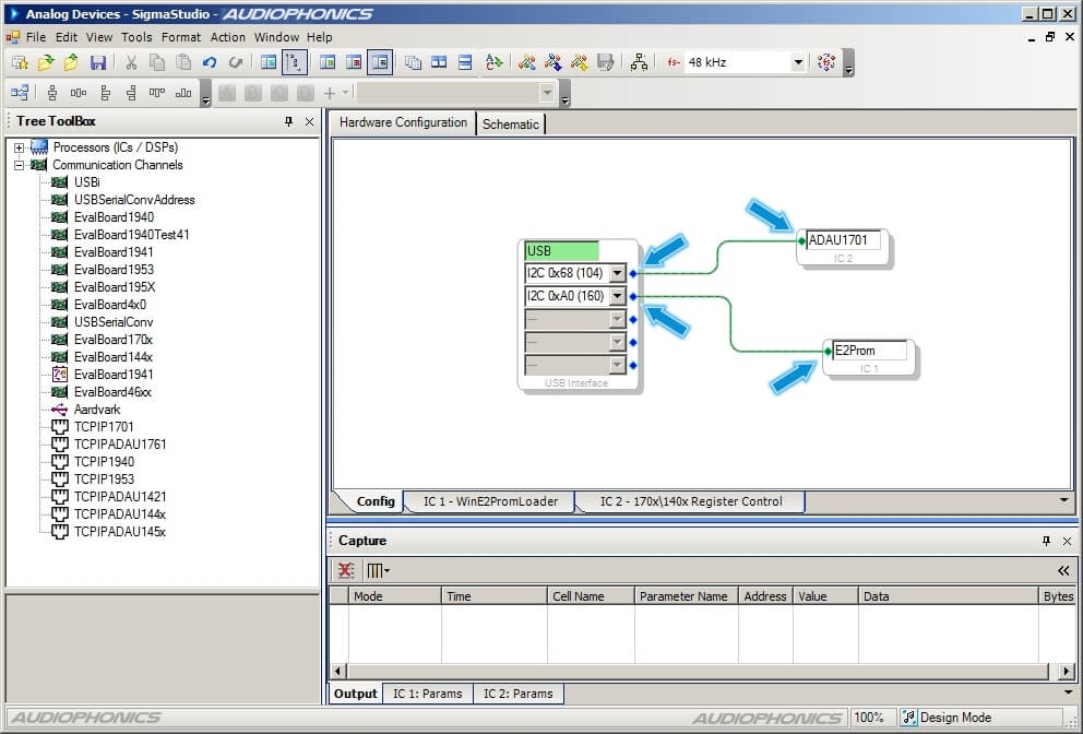
Below the green/red frame, there are 5 grayed lines, each next to a blue square. Drag and drop the blue square to link them to the green square on ADAU1701 and E2Prom. Each port is then automatically set.
Write your DSP algorithm
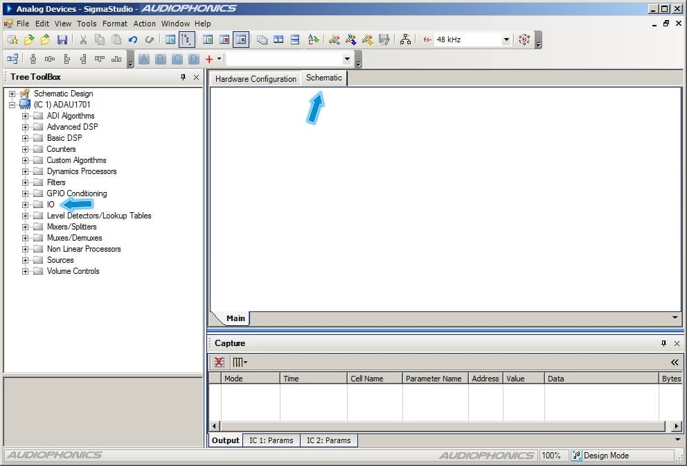
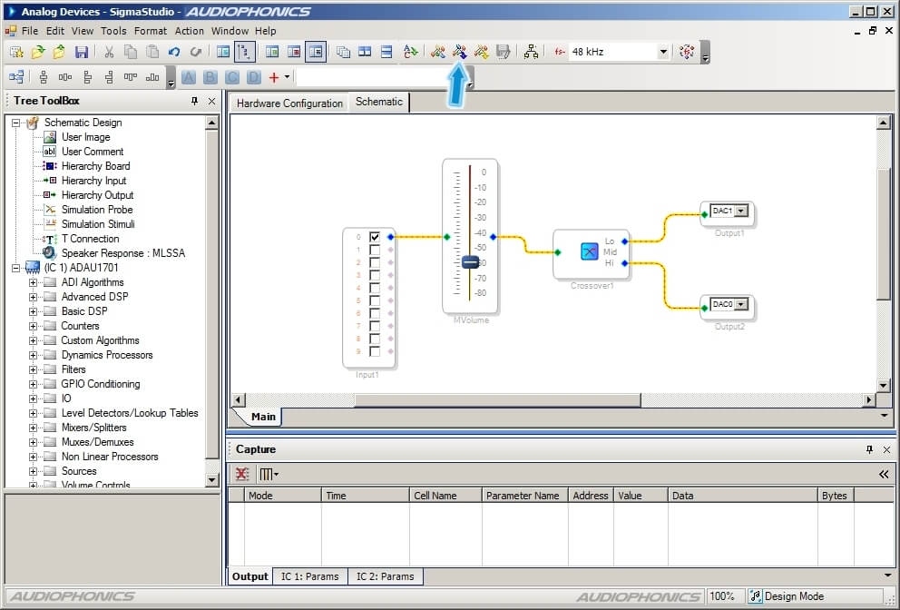
Once your programmer board is set, it is time to tell it what you actually want it to do as far as digital sound processing is concerned. Go to the "Schematic" tab.
Principle is the same, drag and drop the items that you want in your algorithm from the left panel to the right and fill the settings when needed.
The very first step should be to add at least an input and an output for the signal To do this, go to the left panel, open the "IO" entry then "Input". Drag and drop an input item to the graphic editor on the right and do the same with output. (Remember that you will need two inputs / outputs if you want the signal to be stereophonic).
The point of this tutorial is not to tell you how to write your own algorithm. The graphic editor is intuitive enough by itself. Some experience in sound engineering can be of help if you plan to use complex dynamic signal processing. Keep it simple and remember to watch the order of your algorithms (dynamics then equalizer then crossover).
Compiling and uploading your algorithm to the DSP
Once you have you processing algorithm ready, use the IC cable to link the programmer board to the DSP module. (It is OK if it was plugged already).
In Wondom's videos, each of the programmer board and the DSP module have their own power supply (both are powered on micro-USB). However, the programmer board is supposed to be able to power the DSP module, I tried to with only the programmer board powered and everything worked. Maybe it was because my power supply is really strong.
compiling and exporting your algorithm can be frustrating. If absolutely everything is not perfectly in order, Sigma Studio will throw an error. If this happen, unplug the programmer board from the computer, unplug the DSP module from the programmer board and reconnect everything in the order. Even your computer going to stand-by mode for a second can lose the connection.
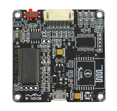
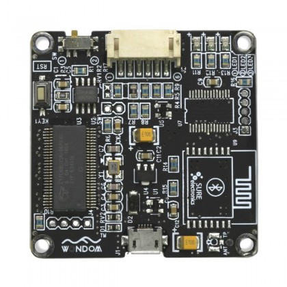
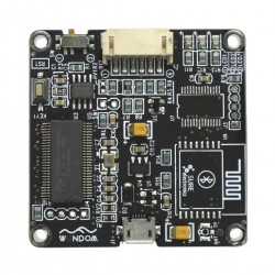
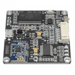
Look closely at the programmer board. On the left to the connector, you will find a 2 position switch (highlighted in red on the picture).
Make sure the switch is in position 1 (left if the IC connector is facing you)
If the switch is not on the right position, you will not be able to edit the DSP inner programmation.
Click on the Link Compile Connect (blue arrow on the picture above) to compile your algorithm. This operation takes your algorithm and convert it to basic instructions for the logical chip ADAU1701 in the DSP.

Note that the last step changed the state of your Sigma Studio Project. The software window now prints : "Ready: Compiled" on the bottom-right corner.
Button "Link Compile Download" purpose is to copy your compiled algorithm in the ADAU1701 flash memory. 90% of the time, this is where error occurs. If you encounter any issue, remember to disconnect and reconnect everything and check the position of the Switch. Make sure the DSP module is connected before trying again.
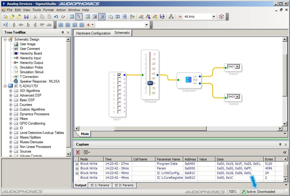
If everything went as expected, the project status changes again and you can read on the bottom right corner : Active: Downloaded.
At this point, your DSP module is already running your algorithm. You can modify the parameters on Sigma Studio Schematic tab but you cannot add / remove or change virtual connections. To do so you will have to repeat compiling and downloading.
If you want to verify quickly that everything works right, you can download a test project here. This very simple algorithm set your DSP module to send a continuous 300Hz square wave signal to the right and left channels. It is a easy way to check that everything is working properly without having to plug an audio source.
Do not unplug the programmer board nor the DSP module yet. At this state, the DSP module still have your algorithm stored in a temporary memory. It will be lost in a few milliseconds if powerline is shut.
Copy the data to EEPROM Memory
Because you do not want to redo all the programming everytime you need the DSP, you need to write your algorithm to the EEPROM (long lasting memory) of your DSP module.
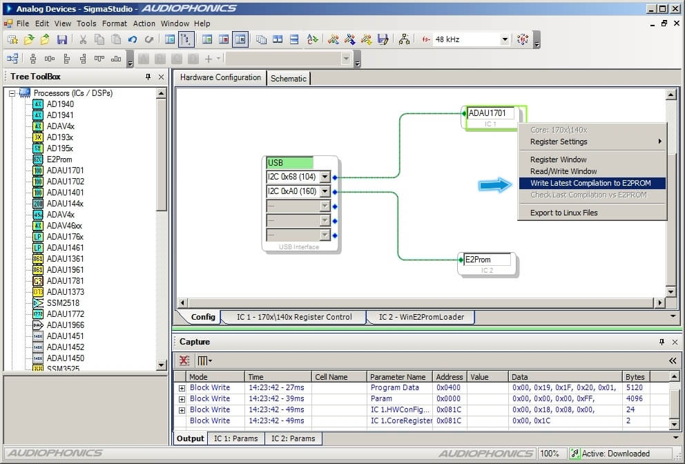
To do that, go back to the "Hardware Configuration" tab and right click on the ADAU1701 element in the graphic editor. If the project state is on "Active : Downloaded" contextual menu nows offer you to " Write Latest Compilation to E2PROM". Click on this option.
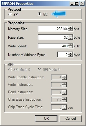
You have done the hardest part. A last menu pops and all you have to do is make sure the selected protocol is I2C before clicking OK to write your algorithm on the EEPROM.
After a short loading bar, the internal memory of your DSP module is now loaded with your configuration. It means that your DSP will run it by itself without the need for a computer or the programmer board.
If you want to modify the configuration of your DSP, just repeat everything (or load your Sigma Studio project). Any new hit on "Write Latest Compilation to E2Prom" erases the former configuration.
Video by Wondom
Produit en rapport avec cet article
Rechercher dans le blog
Blog categories
Latest Comments

Audiophonics Team
on DIY Tutorial - PiCorePlayer - Installing...
Pierre Bommel
on Lecteur réseau Opensource : Solutions
Pierre Bommel
on DIY Tutorial - PiCorePlayer - Installing...
Audiophonics Team
on Tutorial DIY - Power cable ELECAUDIO CS-331B


![[GRADE B] DAYTON AUDIO MKSX4 Low Profil Subwoofer Speaker 160W Ø20cm](https://www.audiophonics.fr/72897-thumb_default/dayton-audio-mksx4-low-profil-subwoofer-speaker-160w-o20cm.jpg)